I enjoyed my very first embedded programming with M5Stack Core2 for AWS after the electrical parts shopping.

Arduino IDE
Arduino is an open-source electronics platform based on easy-to-use design. Because M5Stack hardwares use the same microcontroller as Arduino hardwares, which is called ESP32, Arduino IDE can be used for M5Stack’s embedded software development, too. Arduino IDE supports compiling code and uploading binaries to the M5Stack.
After downloading Arduino IDE, “Additional boards manager URLs” has to be set so that Arduino IDE can include packages provided by M5Stack.
https://m5stack.oss-cn-shenzhen.aliyuncs.com/resource/arduino/package_m5stack_index.json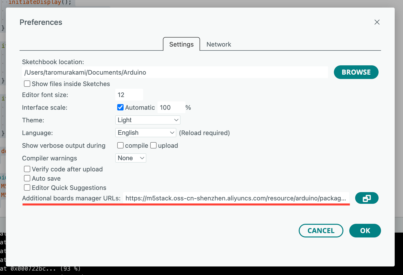
1. Hello World
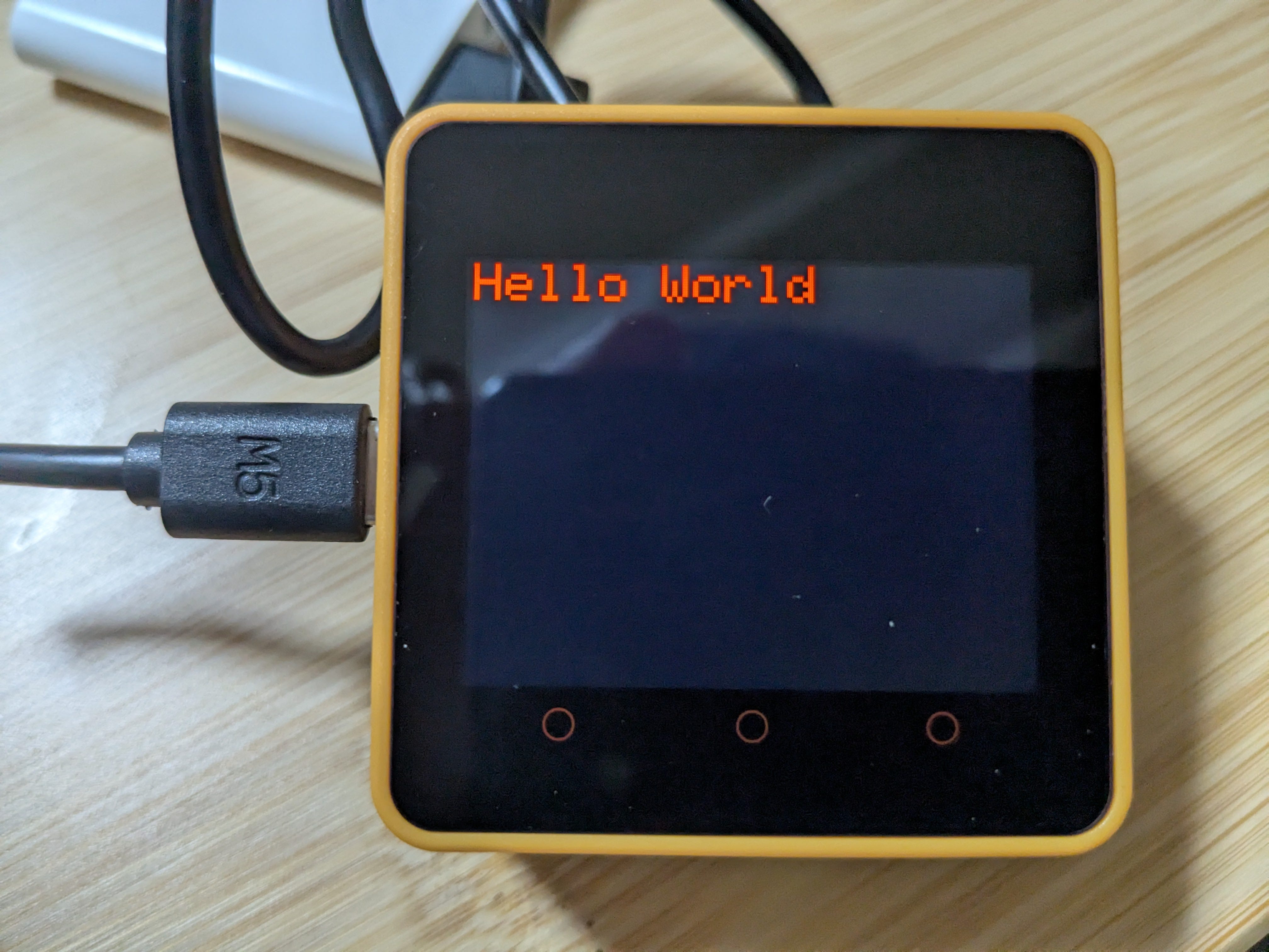
The code below shows "Hello World" on the screen.
#include <M5Core2.h>

void setup() {
  M5.begin();
  M5.Lcd.setTextSize(3);
  M5.Lcd.setTextColor(RED);
  M5.Lcd.print("Hello World");
}

void loop() {
}
Let’s go line-by-line and explain what each part does:
#include <M5Core2.h>
This includes the M5Core2 library, which provides all the functions necessary to interact with the Core2 device (like display, buttons, touch, etc.).
void setup() {
This is the setup function that runs once when the device powers on or resets.
M5.begin();
Initializes the Core2 hardware. It sets up the screen, power management, touch panel, etc.
M5.Lcd.setTextSize(3);
Sets the text size to 3 (default is 1). Larger number means larger font.
M5.Lcd.setTextColor(RED);
Sets the text color to red. RED is a predefined color constant from the library.
M5.Lcd.print("Hello World");
Prints the string "Hello World" to the LCD screen of Core2.
void loop() {}
It’s empty here. Skip it for now.
2. Show message by pushing button
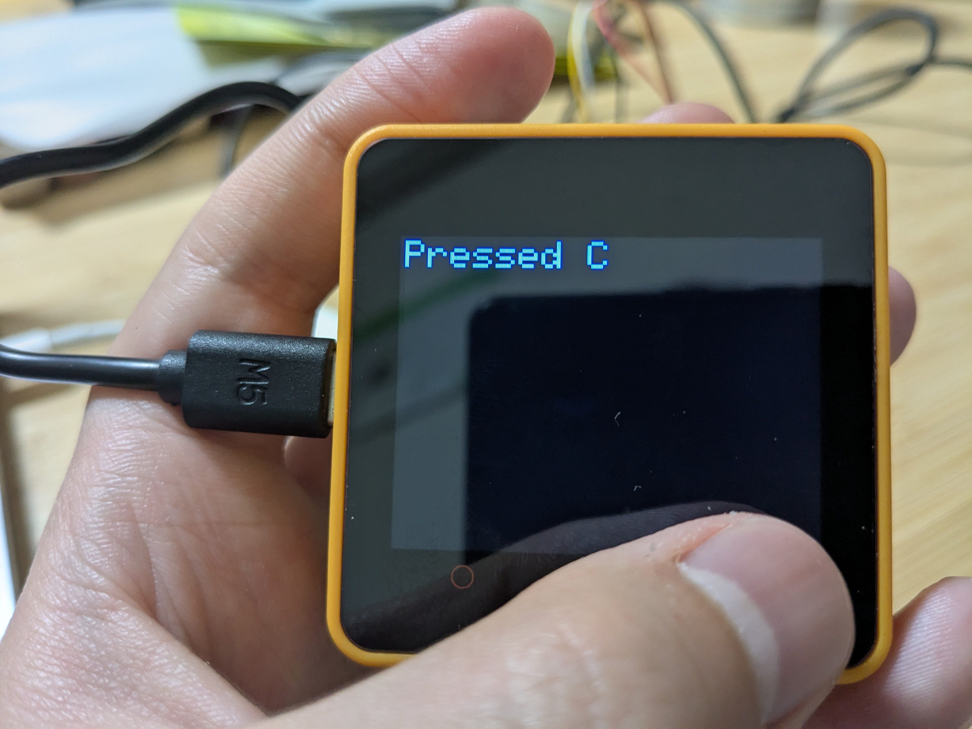
Core2 has 3 buttons below the screen. Those buttons are named “A”, “B” and “C” from left to right. The code below shows a message on the screen when one of the three front buttons (A, B, or C) is pressed accordingly.
#include <M5Core2.h>

void setup() {
  M5.begin();
  M5.Lcd.setTextSize(3);
  M5.Lcd.setTextColor(RED);
  M5.Lcd.print("Hello World");
}

void loop() {
  M5.update();  // Update button status

  if (M5.BtnA.wasPressed()) {
    initiateDisplay();
    M5.Lcd.setTextColor(YELLOW);
    M5.Lcd.print("Pressed A   ");
  }

  if (M5.BtnB.wasPressed()) {
    initiateDisplay();
    M5.Lcd.setTextColor(GREEN);
    M5.Lcd.print("Pressed B   ");
  }

  if (M5.BtnC.wasPressed()) {
    initiateDisplay();
    M5.Lcd.setTextColor(BLUE);
    M5.Lcd.print("Pressed C   ");
  }

  delay(50);  // Small delay to debounce
}

void initiateDisplay() {
  M5.Lcd.clear();
  M5.Lcd.setCursor(0, 0);
}
The loop() function contains the code that the Arduino board executes repeatedly after the setup() function has run once. This continuous execution allows the Arduino to perform tasks such as reading sensor inputs, controlling actuators, and communicating with other devices in real-time.
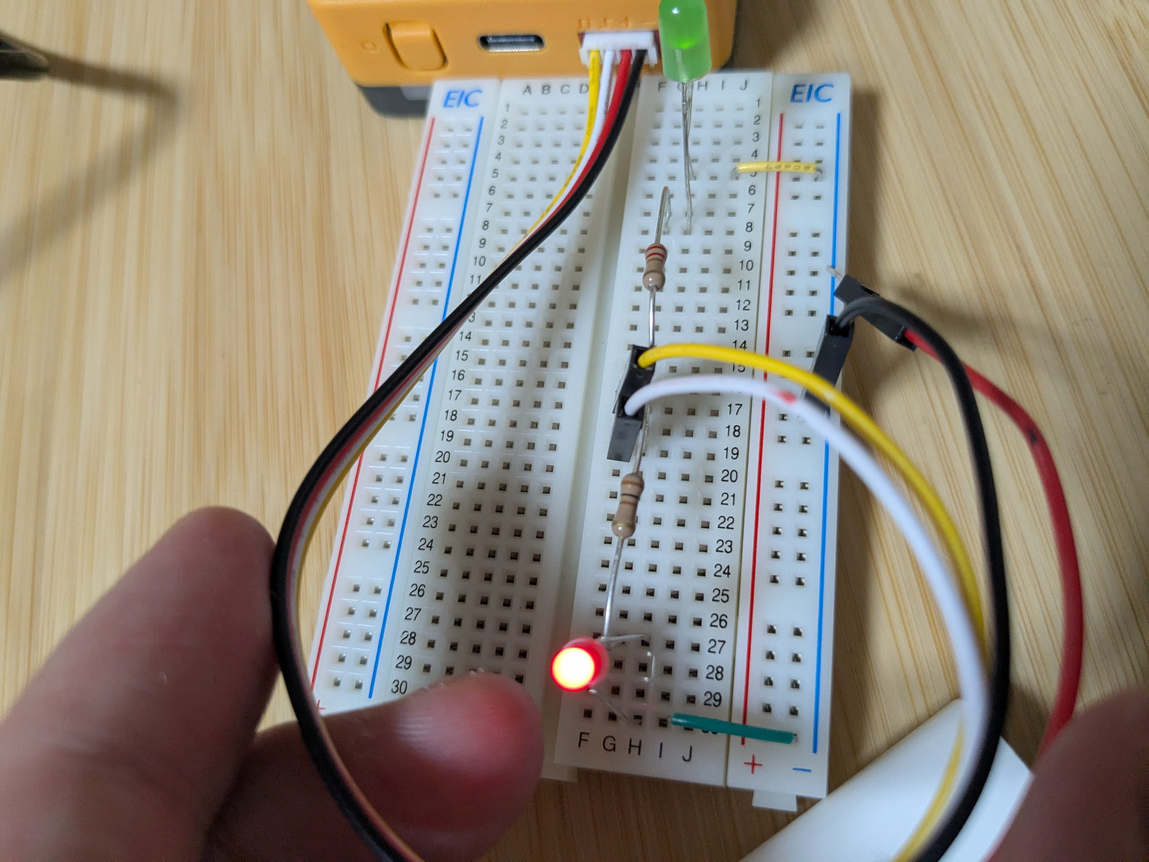
3. Blink LED
Code
The code below controls GPIO port 32 and 33. GPIO stands for General Purpose Input/Output. It can send or receive signal represented by a change in voltage. Because this code changes the voltage of 2 GPIO ports alternately every 500ms, it blinks the green LED and red LED by turns.
#include <M5Core2.h>
#define YELLOW_PIN 32
#define WHITE_PIN 33

void setup() {
  M5.begin(true, true, true, false);
  M5.Lcd.setTextSize(3);
  M5.Lcd.setTextColor(RED);
  M5.Lcd.print("Blink LEDs");

  pinMode(YELLOW_PIN, OUTPUT);
  pinMode(WHITE_PIN, OUTPUT);
}

void loop() {
  digitalWrite(YELLOW_PIN, HIGH);
  digitalWrite(WHITE_PIN, LOW);
  delay(500);

  digitalWrite(YELLOW_PIN, LOW);
  digitalWrite(WHITE_PIN, HIGH);
  delay(500);
}
Circuit
Described a similar circuit by using Tinker CAD. The battery and the switcher corresponds to Core2.
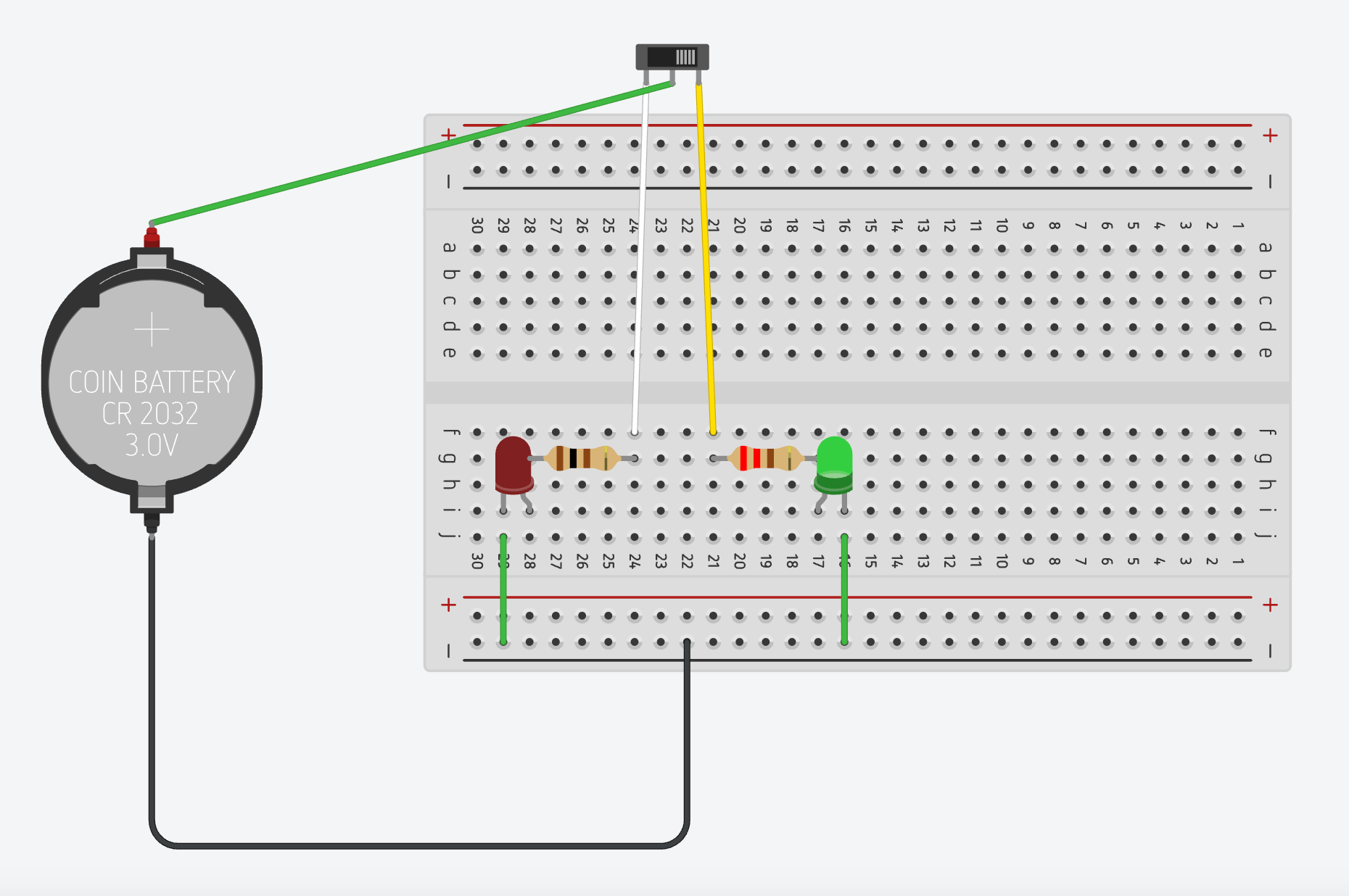
Insert a cable to Port A of Core2.
Port A adopts a Grove Connector system. It’s a standarized 4-pin connector and is designed to simplify the process of connecting sensors, actuators, and other modules to microcontrollers.
So the one edge of the cable is female for Grove, the other side is male for jumper wire.
The yellow cord is for GPIO port 32 and white is for 33.